[Requires paid membership to access.]
by George Dyke….
Yesterday I was working on a 2CV and inadvertently knocked the light switch stalk to the extent that I cracked the housing. The switch was intermittent and I was going to replace it anyway, so I wasn’t shedding a tear about the damage. Much to my surprise the casing that broke away gave a perfect window at the internals of the switch and so I took a few pictures.

The 2CV switch works by rotating a stalk for light control in a sort of “H shift” manner. It has two rotational positions and the stalk itself two physical positions; forward and back. The light positions are as follows:
- Rotate one turn from off “O” (to “V”) with the stalk in forward position = ville (running) lights
- Push the stalk back, leaving at one turn (“V”) = low beam headlights
- Rotate to second point (“R”) from off with the stalk in back position = low beam headlights
- Pull the stalk forward (in second rotational position – “R”) = high beam headlights
If switch is on off “O” position there is no light engagement no matter what position the stalk is in.
Regardless of the above pushing in the stalk (depressing it to the left) will activate the horn.
All in all – a very clever and simple design that works by making the appropriate contact on the electrical conductive surface of the large internal cylindrical section of the stalk. Since there are no relays in a 2CV it is passing full voltage (and amperage) at the contact points. With age these contacts can either wear or become grimy and at that point you end up with an intermittent light switch. If there is not too much wear it can be repaired by cleaning and closing the gap of the contacts, but as replacement switches are readily available from 2CV parts suppliers these days, it’s probably best to fit a new switch.
Since in my case the casing was cracked and the chrome on the stalk corroded, I opted to install a new switch I had on hand. But before tossing out the old switch, I took a few photos to show how it operates:
 Switch in off position.
 Switch in ville (running) lights – stalk forward, one turn ville (“V”) position.
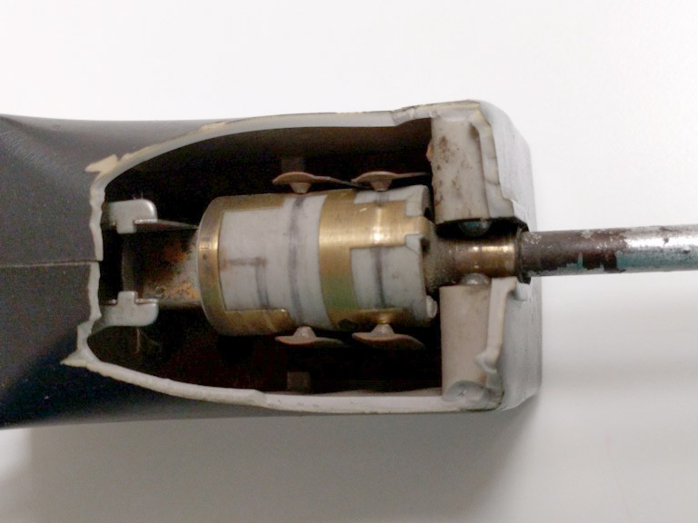
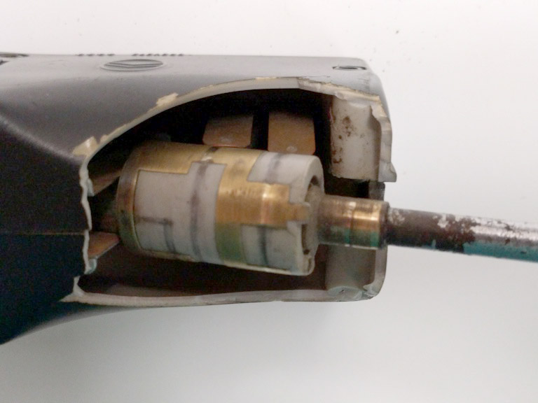
 Switch in low beam headlight on – stalk back, one turn ville (“V”) position.
 Close-up of switch in low beam headlight on – stalk back, one turn ville (“V”) position. (Note the 2 spring mounted ball bearings in the case holding the stalk. This controls and a gives a “click” when moving the stalk from the forward and back positions.)
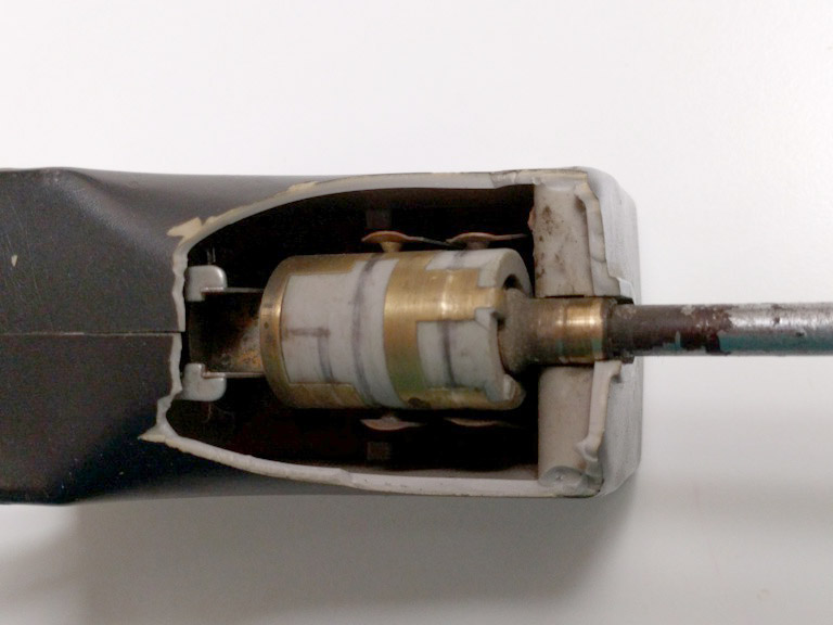
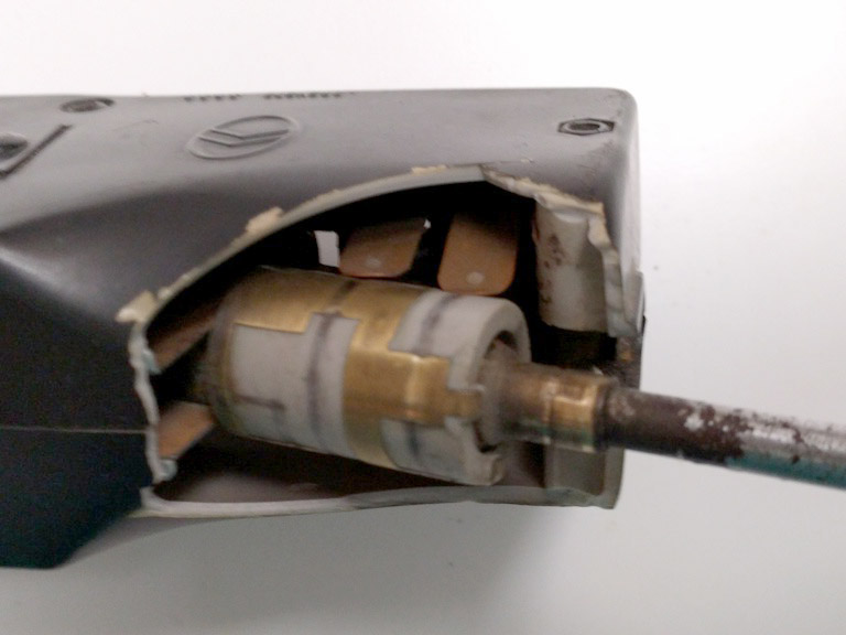
 2nd view close-up of switch in low beam headlight on – stalk back, one turn ville (“V”) position.
 Switch in low beam headlight on – stalk back, shaft back, second rotational (“R”) position.
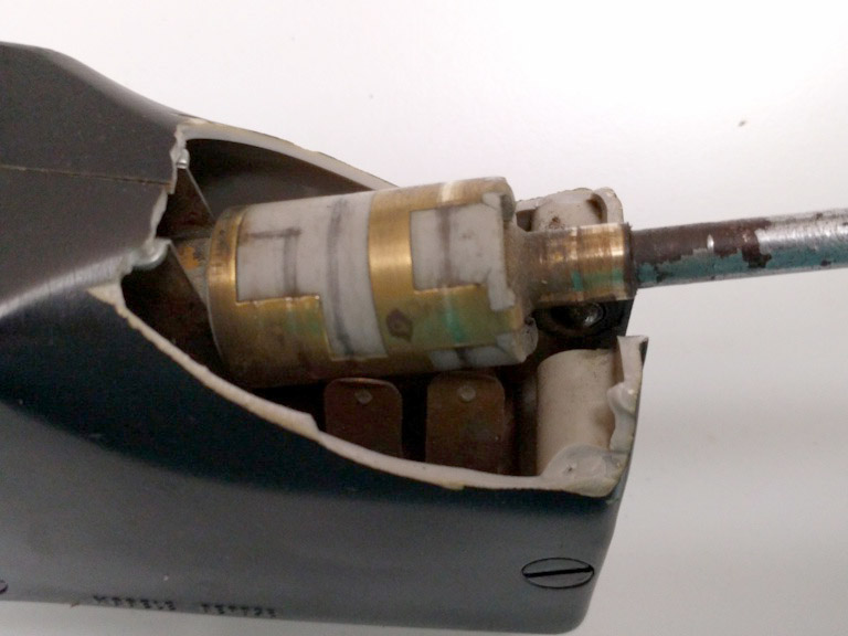
 Close-up view of switch in low beam headlight on – stalk back, second rotational (“R”) position.
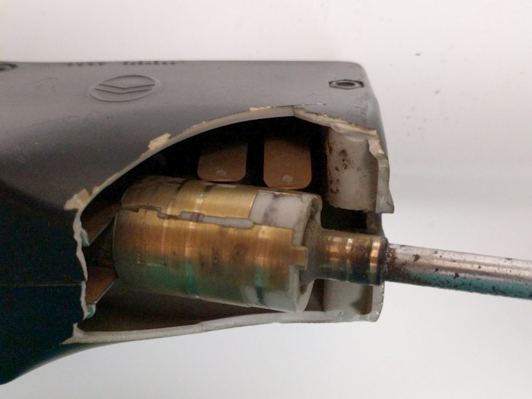
 Close-up view of switch in high beam headlight on – stalk forward, second rotational (“R”) position.
 View of horn contacts.
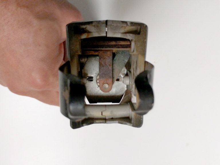
 View of switch pressure levers on square internal section of the stalk for rotational “click” positioning.
 View of 5 connection points on the back of the switch for the 5 wires (lower right nut has no connection).
 4 views of of the stalk extracted from the housing to show contact points.
Thanks for a great review of the guts of the light switch.
Rod Radovanovic
The same switch was used on the Traction Avant and the H vans. I built a new electrical system for my 1939 Traction Avant Commerciale, where I incorporated relays to avoid having full current going through the dashboard switches and to ensure maximum power to the headlights and the electric fan I installed.
The Traction Avant uses all the contact points on the switch. The connection points function like this (seen from below and with the stalk to the right):
Horn 1 High Beam Low Beam
Feed from battery
Horn 2 Rear Lights Parking Lights
One weak point is the contact feeding electricity to the rotating drum. It has to be aligned in the right place and the margin for error is small. If you disassemble the switch, it is a bit tricky to get it back together, getting the drum and all the springy contact points in the right place while you try to get the screws in to hold it together. It is one of those jobs where it would be handy to have a couple of extra hands (if you can find room for them), as everything has a tendency to want to spring apart while you hold it together. But don’t be afraid. All you need is some patience.
Per Ahlstrom
Sorry, the layout changed with the posting, so my explanation of the contact points didn’t work. Here is another explanation: If you look at George’s picture of the bottom of the switch, the contact points are as follows.
To the very left is the feed from the battery/generator
The top row from left to right: Horn 1, High Beam, Low Beam
Bottom row from left to right: Horn 2, Rear Lights, Parking Lights
All of the questions on my mind were answered. I appreciate it so much. Thank you!
Does “push the stalk back” mean “push the stalk forward”? Because if you push it, it will move forward (towards the front of the car).
Same issue with “pull the stork forward”. Do you mean pulling it back, towards the back of the car?
Yes.
Thank you George. Just purchased an ‘83 4/6 and pretty ran though everything mechanical, from cv boots to carburator rebuild to fuel pump. The switch seemed a bit hard to rotate, so I took it apart and cleaned the contacts and lubed where I could. Wanted to make sure I didn’t have the switch reversed 180 degrees. Thanks again for the great photos!